
Struggling to set up a reliable home or office network? Maybe your Ethernet cable isn’t working, or you’re confused about wiring a plug correctly. The RJ45 connector pinout is the key to ensuring fast, stable internet connections. This tiny plug, used in Ethernet cables like Cat5e, Cat6, or Cat6A, follows standards like TIA/EIA-568 to connect devices properly. Without the right pinout, your network could face slow speeds or dropped signals—frustrating, right?
This guide explains the RJ45 pinout, focusing on T568A and T568B wiring standards and why they matter for network performance. Whether you’re a DIY enthusiast or a professional installer, you’ll learn how to wire cables correctly, avoid common mistakes, and boost your network’s efficiency.
We’ll also share tips from industry practices, like minimizing crosstalk for better data transfer. Ready to make your network setup hassle-free? Keep reading to master the RJ45 connector pinout and ensure seamless connectivity.
What is the RJ45 Connector Pinout?
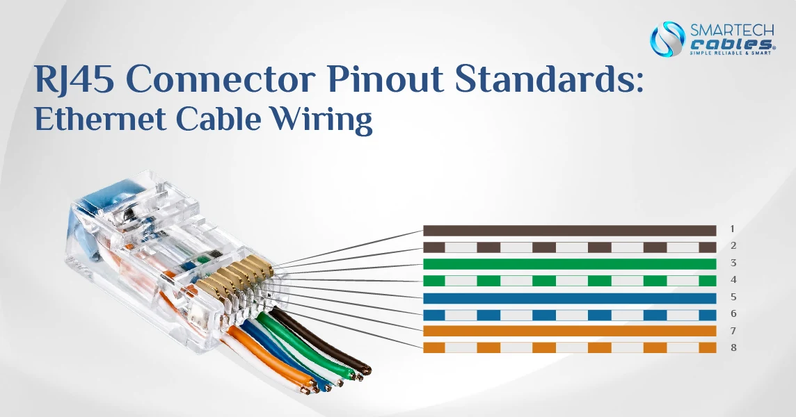
An RJ45 connector pinout is the specific arrangement of eight colored wires inside an Ethernet cable connector. Think of it as a wiring map that tells each wire exactly where to go. You'll see eight metal contacts when you look at an RJ45 connector (the plastic plug at the end of an Ethernet cable). The pinout determines which colored wire connects to each of these metal pins.
Getting this arrangement right is critical for network communication. Data travels through an Ethernet cable and follows specific pathways created by these wire arrangements. Using the wrong pinout is like trying to drive on a road where the lanes are mixed up – traffic simply can't flow properly.
RJ45 Pinout Standards: T568A and T568B Wiring Configurations
Regarding RJ45 connector pinout standards, two main configurations rule the networking world: T568A and T568B. These standards were created by the Telecommunications Industry Association (TIA) and the Electronic Industries Alliance (EIA) to ensure network connections work consistently across all equipment.
T568A RJ45 Wiring Standard Explained
The T568A standard is one of two main wiring schemes for RJ45 connectors. In this configuration, the RJ45 pinout for Ethernet Cable follows this color pattern when looking at the connector with the clip facing away from you:
- White/Green stripe
- Green solid
- White/Orange stripe
- Blue solid
- White/Blue stripe
- Orange solid
- White/Brown stripe
- Brown solid
T568B RJ45 Wiring Schematic and Applications
The T568B standard is slightly different but equally valid. The pin layout for RJ45 follows this colour pattern:
- White/Orange stripe
- Orange solid
- White/Green stripe
- Blue solid
- White/Blue stripe
- Green solid
- White/Brown stripe
- Brown solid
Pin Layout for RJ45: Understanding the 8-Pin Configuration
The 8-pin configuration of RJ45 connectors follows a specific pattern that allows for reliable data transmission. Understanding what each pin does helps troubleshoot network issues or create custom cables.
Pin 1 on RJ45 and Sequential Pin Identification
Finding pin one on an RJ45 connector is the starting point for proper wiring. When looking at the connector with the clip facing down and the pins pointing away from you, pin one is located at the far left. The pins are numbered sequentially from left to right (1 through 8).
A common memory trick for remembering this is "Left is First"—the leftmost pin is always pin 1 when the connector is held in the standard position. This consistent numbering system ensures that network professionals worldwide can communicate clearly about connector wiring.
For female RJ45 jacks (the ports where you plug in the cables), the pin numbering is mirrored; pin 1 will be on the right side when looking directly at the port.
Function of Each Pin in Ethernet Applications
Each pin in an RJ45 connector serves a specific purpose in Ethernet connections. The exact function depends on the Ethernet standard being used:
For 10/100 Mbps Ethernet (the most common in homes and small offices):
- Pins 1 and 2: Transmit data (TX+/TX-)
- Pins 3 and 6: Receive data (RX+/RX-)
- Pins 4, 5, 7, and 8: Unused in basic Ethernet
For Gigabit Ethernet (1000 Mbps):
- All eight pins are used
- Pins 1 and 2: Data pair 1
- Pins 3 and 6: Data pair 2
- Pins 4 and 5: Data pair 3
- Pins 7 and 8: Data pair 4
This is why proper RJ45 connector pin details matter increasingly in high-speed networks, as gigabit connections rely on all pins functioning correctly. In contrast, older or slower networks might still work even with some pins improperly connected.
Troubleshooting Common RJ45 Pinout Issues
Even experienced network technicians encounter wiring problems. Knowing how to identify and fix these issues saves time and frustration.
Testing RJ45 Connections with Cable Testers
A cable tester is an essential tool for verifying RJ45 connector pinout accuracy. These devices check:
- Continuity: Confirms each pin has a complete connection
- Wire mapping: Verifies that pins connect to the correct corresponding pins
- Shorts: Detects unwanted connections between wires
- Opens: Identifies broken connections
- Split pairs: Finds wires connected to incorrect pins
- Length: Many advanced testers can measure cable length
Basic cable testers use LED lights to indicate connection status, while professional models provide detailed diagnostic information, including the distance to faults and advanced measurement capabilities.
Testing should be standard practice after creating any cable. A quick test can prevent hours of network troubleshooting later.
Conclusion
Understanding RJ45 connector pinouts is essential for reliable network installations. Whether you're a DIY enthusiast setting up a home network or an IT professional managing enterprise systems, following industry standards ensures your connections will perform consistently and reliably.
By following these guidelines and understanding the RJ45 connector pinout fundamentals covered in this guide, you'll create reliable network connections that deliver the performance your digital life demands.
Have you tackled your own Ethernet cable projects? Share your experiences or questions in the comments below—we'd love to hear about your network wiring adventures!
FAQs:
What is the function of the RJ45 connector pin?
RJ45 connector pins create electrical connections between networked devices. In standard Ethernet, pins 1, 2, 3, and 6 carry data signals (transmit and receive pairs), while in Gigabit Ethernet, all eight pins are used to achieve higher speeds. Each pin must connect to its corresponding pin on the other end of the cable for proper communication.
What is a cable pinout?
A cable pinout is a diagram or specification showing how wires inside a cable connect to pins in the connector. It's essentially a wiring map that ensures data signals follow the correct paths between devices. Standard pinouts (T568A/B) ensure compatibility for Ethernet cables across different equipment manufacturers.
What does RJ45 stand for?
RJ45 stands for "Registered Jack 45." It's part of a series of telecommunications interface standards. Technically, the connector commonly called RJ45 is an 8P8C (8 Position, 8 Contact) connector, but "RJ45" has become the standard term used throughout the networking industry.
Can I use the same pinout for phone and Ethernet connections?
No, you should not use the same pinout. While an RJ45 connector might physically fit into a phone jack (RJ11), the pinout is different. Phone systems typically use the centre pins of an RJ11 connector, while Ethernet uses specific pin pairs in an RJ45 connector. Using Ethernet pinouts for phone connections may damage equipment or create unreliable connections.
How do I identify Pin 1 on an RJ45 connector?
When holding an RJ45 connector with the clip facing down and the pins pointing away from you, Pin 1 is on the far left. The pins number sequentially from left to right (1 through 8). On RJ45 jacks, when looking directly at the port, Pin 1 is typically on the right side.